
Quick Answer
NEC Chapter 9 contains the tables electricians use to calculate conduit fill correctly.
Table 1 tells you the maximum conduit fill percentage, Table 4 provides the internal area of different conduit types, Table 5 lists the area of insulated conductors, and Table 8 contains the dimensions and electrical properties of bare conductors. When used together, these tables help you choose the correct conduit size and meet NEC requirements. If you want to save time, you can also use our Conduit Fill Calculator to perform these calculations automatically.
What Is NEC Chapter 9?
NEC Chapter 9 is a reference section of the National Electrical Code. Instead of giving installation rules, it provides the data needed to perform electrical calculations.
One of its most common uses is conduit fill.
When you install wires inside a conduit, you cannot fill it completely. The NEC limits how much space the conductors can occupy to make pulling wires easier and to reduce the risk of overheating.
Chapter 9 provides the measurements needed to calculate that space accurately.
If you’re new to this topic, our guide on What Is Conduit Fill? explains why conduit fill matters and how it affects electrical safety.
Why NEC Chapter 9 Is Important
Every electrical installation starts with proper planning.
Choosing a conduit that is too small can make wire pulling difficult and may even create a code violation. Choosing one that is much larger than necessary increases material costs without adding any real benefit.
NEC Chapter 9 helps you find the right balance.
It allows you to:
- Select the correct conduit size.
- Prevent overcrowded raceways.
- Follow NEC conduit fill requirements.
- Reduce installation problems.
- Pass electrical inspections with confidence.
Whether you’re working with EMT, PVC, IMC, or RMC conduit, these tables provide the information needed for accurate calculations.
If you’re unsure which raceway is best for your project, our EMT vs PVC vs IMC Conduit guide compares the most common conduit types.
How NEC Chapter 9 Tables Work Together
Many people think they only need one table.
In reality, the tables work as a team.
You normally follow this order:
| Step | Table | Purpose |
|---|---|---|
| 1 | Table 1 | Find the maximum conduit fill percentage. |
| 2 | Table 5 | Find the area of insulated conductors. |
| 3 | Table 4 | Find the conduit’s internal area. |
| 4 | Table 8 | Use when working with bare conductors or conductor properties. |
After gathering this information, you compare the conductor area with the available conduit area to see whether the installation meets NEC requirements.
If you prefer a detailed walkthrough, see our guide on How to Calculate Conduit Fill Step by Step.
NEC Chapter 9 Tables at a Glance
Before looking at each table individually, here’s a quick overview.
| NEC Table | What It Contains | When You Use It |
|---|---|---|
| Table 1 | Maximum conduit fill percentages | Every conduit fill calculation |
| Table 4 | Internal dimensions of conduit | Selecting conduit size |
| Table 5 | Area of insulated conductors | Calculating conductor space |
| Table 8 | Bare conductor dimensions and electrical properties | Advanced calculations and bare conductors |
Each table answers a different question.
Together, they provide everything needed for a conduit fill calculation.
NEC Chapter 9 Table 1 Explained
Table 1 is the starting point for almost every conduit fill calculation.
It tells you the maximum percentage of the conduit that conductors can occupy.
Instead of allowing installers to fill a conduit completely, the NEC limits the available space. This leaves enough room for easier wire pulling, better heat dissipation, and future maintenance.
Without Table 1, every conduit could end up being packed differently, leading to inconsistent installations.
Maximum Conduit Fill Percentages
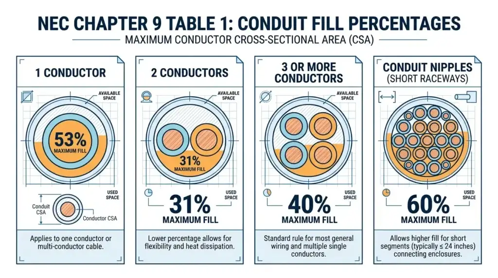
Table 1 contains four values that electricians use every day.
| Number of Conductors | Maximum Fill |
|---|---|
| 1 conductor | 53% |
| 2 conductors | 31% |
| 3 or more conductors | 40% |
| Nipples 24 inches or less | 60% |
These percentages apply to the conduit’s internal cross-sectional area, not its outside diameter.
If you’ve ever wondered why most conduit fill calculations use the 40% rule, our article explaining Why the NEC Limits Conduit Fill to 40% covers the engineering reasons behind this requirement.
Why Are the Fill Percentages Different?
The percentages are based on how conductors behave inside a conduit.
A single conductor has plenty of room to move, so it can occupy more space.
With two conductors, the wires tend to twist during installation. This increases pulling resistance, so the allowed fill drops to 31%.
When three or more conductors are installed, they usually move together as a bundle. Because of this, the NEC allows the fill to increase to 40%.
Short conduit nipples are a special case. Since they are no longer than 24 inches, pulling tension is much lower, allowing up to 60% fill.
When Do You Use Table 1?
Table 1 should be your first stop whenever you’re calculating conduit fill.
You’ll use it for:
- Residential wiring.
- Commercial electrical systems.
- Industrial installations.
- Feeder circuits.
- Branch circuits.
- Service conductors.
No matter which conduit material you choose, Table 1 provides the fill percentage before you move to the remaining Chapter 9 tables.
Common Mistakes With Table 1
One of the biggest mistakes is forgetting to count the equipment grounding conductor.
Ground wires still take up space inside the conduit, so they must be included in the calculation.
Another common mistake is assuming every installation uses the 40% rule.
That is only true when three or more conductors are installed.
If there is only one conductor, or exactly two conductors, different limits apply.
Finally, remember that the 60% rule is only for conduit nipples that are 24 inches long or less. It does not apply to standard conduit runs.
Table 1 Is Only the Beginning
Table 1 tells you how much of the conduit you can fill.
It does not tell you the actual size of the conduit or the space each conductor occupies.
For that, you’ll need Tables 4 and 5.
In the next section, we’ll look at Table 4 and learn how to determine the internal area of EMT, PVC, IMC, and other conduit types before combining everything into a complete conduit fill calculation.
NEC Chapter 9 Table 4 Explained
After finding the maximum fill percentage in Table 1, the next step is to determine how much space is available inside the conduit.
That’s where Table 4 comes in.
Table 4 lists the internal dimensions and cross-sectional area of different conduit types. Without it, you cannot determine whether your conductors will fit inside the raceway.
This table is one of the most frequently used sections in NEC Chapter 9.
What Information Does Table 4 Provide?
Each conduit type has its own section in Table 4.
You’ll find information for common raceways such as:
- EMT
- IMC
- RMC
- PVC Schedule 40
- PVC Schedule 80
- ENT
- FMC
- LFMC
For every trade size, the table includes the conduit’s internal area and the maximum allowable area based on the fill percentages from Table 1.
How to Read Table 4
Using Table 4 is easier than many people think.
Start by identifying the conduit material you’re installing.
Next, locate the correct trade size.
Finally, read the internal cross-sectional area.
That value tells you how much total space the conduit has before applying the fill percentage from Table 1.
Once you know that number, you can compare it with the total area of your conductors.
Why Different Conduit Types Have Different Areas
Many beginners assume all 1-inch conduits have the same internal space.
They don’t.
Even though two conduits share the same trade size, the wall thickness can be very different.
Thicker walls leave less room for conductors.
Here’s a simple comparison.
| Conduit Type | Internal Area | Why It Differs |
|---|---|---|
| EMT | Larger | Thin metal wall |
| PVC Schedule 40 | Usually larger | Thinner wall |
| PVC Schedule 80 | Smaller | Thick wall for extra protection |
| RMC | Smaller | Heavy-duty steel wall |
| IMC | Between EMT and RMC | Medium wall thickness |
This is why you should never use the dimensions from one conduit type for another.
If you’re deciding between conduit materials, our EMT vs PVC Conduit guide explains how they compare in strength, cost, and installation.
Example of Using Table 4
Imagine you’re installing EMT conduit.
After adding the area of all conductors, you calculate a total conductor area of 0.52 square inches.
You then open Table 4 and find the internal area of your chosen EMT conduit.
If the conduit provides enough usable area after applying the fill percentage from Table 1, your installation meets the NEC requirement.
If not, you’ll need the next larger conduit size.
The process is simple once you understand how the tables connect.
Common Mistakes With Table 4
One common mistake is selecting the wrong conduit type.
Using EMT values for PVC can produce the wrong result.
Another mistake is confusing trade size with the actual inside diameter.
A 1-inch conduit is only a trade name. It does not mean the inside diameter is exactly one inch.
Some installers also forget that different schedules of PVC have different internal dimensions.
Always verify the conduit type before reading Table 4.
NEC Chapter 9 Table 5 Explained
Once you know how much space is available inside the conduit, the next question is simple.
How much space does each conductor occupy?
Table 5 answers that question.
Instead of measuring every wire yourself, Table 5 lists the approximate cross-sectional area of insulated conductors.
These values make conduit fill calculations much faster and more consistent.
What Is Included in Table 5?
Table 5 contains conductor sizes from small AWG wires to large kcmil conductors.
It also lists different insulation types because insulation changes the outside diameter of a wire.
For example, a 12 AWG conductor with THHN insulation does not occupy the same space as a 12 AWG conductor with thicker insulation.
Even though the copper conductor is the same size, the insulation changes the total area.
Why Insulation Matters
Many people only look at the wire size.
That is a mistake.
Conduit fill calculations use the outside area of the insulated conductor, not just the copper inside it.
Different insulation types have different thicknesses.
That means two wires with the same AWG size may require different conduit sizes.
Here’s a simple comparison.
| Insulation Type | Space Required | Common Applications |
|---|---|---|
| THHN/THWN | Smaller | General building wiring |
| XHHW | Slightly larger | Feeders and industrial work |
| THW | Larger | Older installations |
| RHH | Larger | High-temperature applications |
Always verify the insulation marking printed on the conductor before using Table 5.
How to Use Table 5
The process only takes a few steps.
First, find the conductor size.
Next, locate the correct insulation type.
Finally, read the conductor area.
Repeat this for every conductor in the raceway.
Then add all the conductor areas together.
That total will later be compared with the available conduit area from Table 4.
Example
Suppose your conduit contains:
- Three 12 AWG THHN conductors
- One 12 AWG neutral
- One 12 AWG equipment grounding conductor
Since all five conductors are the same size and insulation type, you only need to find the area once.
Multiply that value by five.
Now you have the total conductor area.
The remaining step is comparing it with the conduit area from Table 4.
Can You Use Table 5 for Every Conductor?
Most of the time, yes.
However, there are exceptions.
Table 5 is intended for insulated conductors.
If you’re working with bare conductors or need conductor properties such as resistance or stranding, you’ll use Table 8 instead.
We’ll cover that next.
Common Mistakes With Table 5
Many conduit fill errors begin here.
Some of the most common include:
- Using the wrong insulation column.
- Ignoring insulation type completely.
- Mixing conductor sizes without calculating each one separately.
- Assuming all 12 AWG wires occupy the same amount of space.
These mistakes may seem small, but they can change the required conduit size.
If you’d like to avoid these and other calculation errors, our guide on Common Conduit Fill Calculation Mistakes covers the issues inspectors see most often.
How Tables 1, 4, and 5 Work Together
By now, you have three important pieces of information.
Table 1 tells you the maximum fill percentage.
Table 4 tells you how much space the conduit has.
Table 5 tells you how much space the conductors require.
Once you combine these values, you can determine whether the conductors fit safely inside the conduit.
Only one table remains.
Table 8 adds another layer of information for bare conductors and advanced electrical calculations.
In the next section, we’ll explain when Table 8 is required, how it differs from Table 5, and walk through a complete conduit fill calculation from start to finish.
NEC Chapter 9 Table 8 Explained
Table 8 is often misunderstood.
Many people assume it is another conduit fill table. In reality, it serves a different purpose.
While Table 5 focuses on insulated conductors, Table 8 provides information about bare conductors and their electrical properties.
It also includes values used in calculations beyond conduit fill, such as voltage drop and conductor resistance.
If you’re performing a standard conduit fill calculation with THHN, THWN, XHHW, or similar insulated conductors, you’ll usually use Table 5 instead of Table 8.
What Information Does Table 8 Include?
Table 8 contains several conductor properties.
These include:
| Property | Why It Matters |
|---|---|
| Conductor size | Identifies the wire size |
| Bare conductor diameter | Used for bare conductor calculations |
| Cross-sectional area | Helps determine conductor dimensions |
| DC resistance | Used for voltage drop calculations |
| AC resistance | Used for electrical system design |
| Stranding information | Shows conductor construction |
Although not every electrician uses all of these values daily, engineers and designers often rely on them for larger electrical projects.
When Should You Use Table 8?
Table 8 is commonly used when working with:
- Bare copper conductors.
- Bare aluminum conductors.
- Grounding conductors without insulation.
- Voltage drop calculations.
- Electrical resistance calculations.
- Engineering design work.
If your project only involves insulated conductors inside conduit, Table 5 is usually the correct reference.
Table 5 vs Table 8
This is one of the most common questions electricians ask.
The tables may seem similar, but they serve different purposes.
| Table 5 | Table 8 |
|---|---|
| Insulated conductors | Bare conductors |
| Includes insulation area | Does not include insulation |
| Used for conduit fill | Used for conductor properties |
| Most common for electricians | Common for engineers and designers |
The easiest way to remember the difference is this:
If the conductor has insulation, start with Table 5.
If the conductor is bare or you need electrical properties like resistance, use Table 8.
Do You Always Need Table 8?
No.
Many conduit fill calculations never require it.
For example, if you’re installing THHN conductors inside EMT conduit, you’ll normally use:
- Table 1
- Table 4
- Table 5
Table 8 only becomes necessary when your project specifically involves bare conductors or electrical design calculations.
Complete Conduit Fill Calculation Example
Now let’s put everything together.
Imagine you’re installing five THHN conductors inside EMT conduit.
Your goal is to find the minimum conduit size that meets NEC requirements.
Step 1: Count the Conductors
You have:
- Three phase conductors.
- One neutral conductor.
- One equipment grounding conductor.
That gives you a total of five conductors.
Since there are more than three conductors, Table 1 allows a maximum conduit fill of 40%.
Step 2: Find the Conductor Area
Open Table 5.
Locate the conductor size and insulation type.
Find the area for one conductor.
Multiply it by five.
You now have the total conductor area.
Step 3: Find the Conduit Area
Open Table 4.
Locate the EMT section.
Find the conduit size you’re considering.
Read the internal cross-sectional area.
Step 4: Compare the Numbers
Now compare:
Total conductor area
vs.
Maximum allowable conduit area.
If the conductor area is below the allowed limit, the conduit size is acceptable.
If not, move to the next larger conduit.
Step 5: Verify Your Result
Double-check:
- Conductor count.
- Conduit type.
- Wire insulation.
- Fill percentage.
- Final conduit size.
Taking a minute to verify your work can prevent expensive mistakes during installation.
If you prefer a faster method, our Conduit Fill Chart lets you quickly compare common wire and conduit combinations before performing detailed calculations.
How All Four Tables Work Together
The easiest way to understand NEC Chapter 9 is to think of it as a simple workflow.
| Table | Question It Answers |
|---|---|
| Table 1 | How full can the conduit be? |
| Table 5 | How much space do the conductors need? |
| Table 4 | How much space does the conduit provide? |
| Table 8 | What are the properties of bare conductors? |
Each table solves one part of the calculation.
Together, they provide everything needed for an accurate conduit fill calculation.
Common NEC Chapter 9 Mistakes
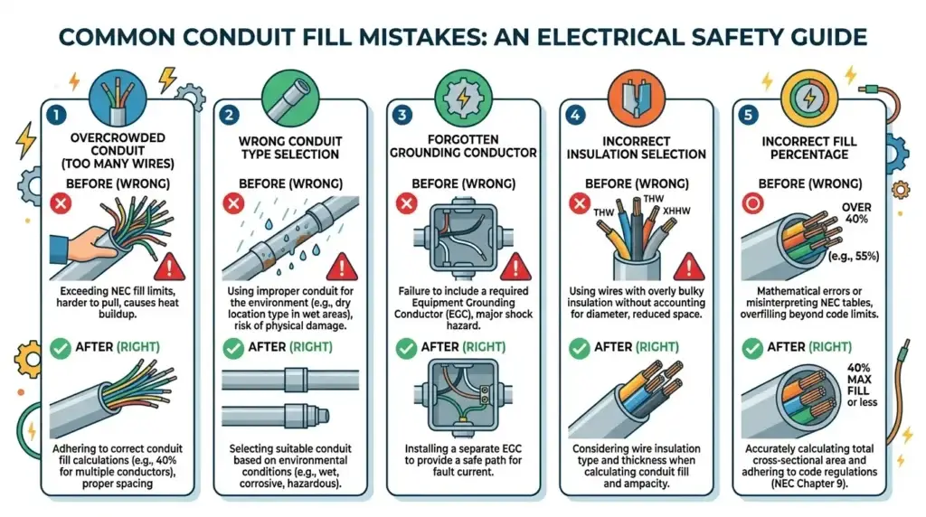
Even experienced electricians occasionally make mistakes when using Chapter 9.
Most of these errors are easy to avoid once you know what to look for.
| Mistake | Why It’s Wrong | Correct Approach |
|---|---|---|
| Using the wrong conduit type | Internal areas are different | Always use the correct section of Table 4 |
| Ignoring insulation type | Wire area changes | Check the conductor marking before using Table 5 |
| Forgetting the ground wire | It still occupies space | Include equipment grounding conductors in the calculation |
| Using 40% for every job | Fill percentage depends on conductor count | Start with Table 1 |
| Confusing Table 5 with Table 8 | They serve different purposes | Use the correct table for your conductors |
| Assuming trade size equals inside diameter | Trade size is only a name | Always use the dimensions listed in Table 4 |
Many of these mistakes can lead to conduit that is too small, making wire pulling difficult and increasing the chance of failing an inspection.
Tips for Using NEC Chapter 9 Faster
After performing a few conduit fill calculations, you’ll notice a pattern.
Most electricians follow the same routine every time.
Start by identifying the conductor size and insulation.
Next, determine how many conductors will share the conduit.
Then find the correct conduit type and compare the available space.
Finally, verify the result before beginning the installation.
Once you understand this process, calculations become much faster.
For projects with mixed conductor sizes or multiple conduit types, using a calculator can reduce both time and calculation errors while still following NEC Chapter 9.
When Should You Use a Conduit Fill Calculator?
Manual calculations are still important because they help you understand how NEC Chapter 9 works.
However, many electricians use a calculator to save time on everyday jobs.
A good conduit fill calculator automatically:
- Applies the correct fill percentage.
- Uses the correct conductor dimensions.
- References the proper conduit size.
- Reduces calculation mistakes.
- Produces results in seconds.
The calculator doesn’t replace NEC Chapter 9. It simply performs the same calculations much faster using the values found in the tables.
Frequently Asked Questions
NEC Chapter 9 is the reference section of the National Electrical Code that contains tables used for electrical calculations. For conduit fill, it provides the fill percentages, conduit dimensions, conductor areas, and other data needed to size raceways correctly.
Table 1 tells you the maximum percentage of a conduit that conductors are allowed to occupy.
The permitted fill depends on the number of conductors inside the raceway.
Table 4 lists the internal dimensions and cross-sectional area of different conduit types, including EMT, IMC, RMC, PVC Schedule 40, and PVC Schedule 80.
You use this table to determine whether your chosen conduit has enough space for the conductors.
Table 5 provides the approximate cross-sectional area of insulated conductors.
Because insulation thickness varies, conductors with the same AWG size may occupy different amounts of space depending on the insulation type.
Table 8 contains information about bare conductors, including diameter, cross-sectional area, stranding, and electrical resistance.
It is mainly used for bare conductor calculations and electrical design work rather than standard conduit fill calculations.
Table 5 is used for insulated conductors and is the primary reference for conduit fill calculations.
Table 8 focuses on bare conductors and electrical properties such as resistance and conductor diameter.
Most conduit fill calculations use three tables together.
Table 1 determines the maximum fill percentage.
Table 4 provides the conduit’s internal area.
Table 5 provides the area of insulated conductors.
Table 8 is only needed for bare conductors or certain engineering calculations.
Yes.
Equipment grounding conductors take up space inside the conduit and must be included when calculating conduit fill.
Leaving them out can produce an incorrect conduit size.
The NEC is updated every three years.
Although the structure of Chapter 9 usually remains similar, conductor types, notes, and technical values can change between editions.
Always verify which NEC edition has been adopted in your area before beginning a project.
You can use a conduit fill calculator, but the calculator still relies on the values provided in NEC Chapter 9.
Understanding the tables helps you verify the results and better understand how conduit sizing works.
It depends on both the conduit material and its trade size.
For the same trade size, PVC Schedule 40 often has a larger internal area than PVC Schedule 80 because it has thinner walls.
Always verify the exact dimensions in Table 4 instead of making assumptions.
A calculator can provide accurate results if it uses the correct values from NEC Chapter 9.
However, you should always review the results and ensure they match the code edition required by your local jurisdiction.
Key Takeaways
Before finishing, here’s a quick recap of what you’ve learned.
| NEC Table | Main Purpose | Used During |
|---|---|---|
| Table 1 | Maximum conduit fill percentage | Beginning of the calculation |
| Table 4 | Conduit dimensions and internal area | Choosing conduit size |
| Table 5 | Area of insulated conductors | Calculating conductor space |
| Table 8 | Bare conductor dimensions and electrical properties | Advanced calculations |
Remember that no single table provides the complete answer.
Each one contributes a different piece of the calculation.
When used together, they help you choose the correct conduit size while meeting NEC requirements.
Conclusion
NEC Chapter 9 is the key reference for accurate conduit fill calculations. Each table has a specific purpose. Table 1 provides the maximum fill percentage, Table 4 lists conduit dimensions, Table 5 covers insulated conductor areas, and Table 8 includes bare conductor properties.
Once you understand how these tables work together, choosing the correct conduit size becomes much easier. Instead of relying on guesswork, you can make code-compliant decisions with confidence.
If you want to speed up the process, use our Conduit Fill Calculator to perform accurate calculations in seconds. You can also refer to our Conduit Fill Chart for a quick lookup of common wire and conduit combinations