
IMPORTANT
Quick Answer: Electrical Nonmetallic Tubing (ENT), universally known in the electrical trade as Smurf Tube, is a pliable, corrugated PVC raceway governed by NEC Article 362. Under NEC Chapter 9, Table 1, three or more conductors installed in ENT are strictly limited to a maximum 40 percent cross-sectional area fill (53 percent for 1 conductor, 31 percent for 2 conductors, and 60 percent for short nipples $\le 24$ inches).
Because ENT is corrugated, its internal diameter is slightly smaller than EMT. Consult the dedicated ENT column in NEC Chapter 9, Table 4 for exact area calculations. Furthermore, because ENT is completely nonmetallic, a separate green copper equipment grounding conductor (EGC) is mandatory under NEC 362.60 and must always be counted toward conduit fill.
Key Takeaways for Electricians & Inspectors
- Corrugated ID Differences: ENT internal dimensions differ from metallic EMT and rigid PVC. A 1/2-inch ENT has an allowable 40 percent fill area of 0.114 square inches (accommodating up to seven 12 AWG THHN conductors per NEC Annex C Table C.2), whereas 1/2-inch EMT provides 0.122 square inches (nine conductors).
- Hand-Biddable & Pliable: ENT flexes smoothly by hand without mechanical conduit benders or heating blankets, reducing rough-in labor by up to 40 percent in residential and commercial framing.
- Color-Coded Identification: Blue ENT designates 120V/240V/277V power branch circuits; Yellow ENT designates low-voltage data and communications (Cat6, coaxial); Orange ENT designates optical fiber raceways.
- Concrete Slab Approved: NEC 362.10(6) explicitly permits ENT encased in poured concrete slabs (both on grade and above grade) provided concrete-tight snap-in fittings are installed.
- Strict Prohibitions: ENT is prohibited from direct burial in earth (NEC 362.12(1)), exposed outdoor sunlight (NEC 362.12(7)), ambient temperatures exceeding 50°C / 122°F (NEC 362.12(3)), and hazardous classified locations.
- 3-Foot Support Rule: ENT must be securely fastened within 3 feet (900 mm) of every box or enclosure, and supported at intervals not exceeding 3 feet along the run (NEC 362.30(A)).
- Mandatory Ground Wire: ENT cannot serve as an equipment grounding path. A dedicated green copper ground wire sized per NEC 250.122 is mandatory and must be included in your 40 percent fill calculation.
What Is ENT Conduit (Smurf Tube)?
Electrical Nonmetallic Tubing (ENT) is a corrugated, pliable raceway manufactured from high-impact, flame-retardant polyvinyl chloride (PVC). Its signature bright blue color on job sites earned it the permanent trade moniker Smurf Tube.
Unlike Schedule 40 or Schedule 80 PVC pipes that require heat boxes to bend, or metallic EMT that demands mechanical hand benders, ENT can be routed around wood framing studs, open steel joists, dropped ceilings, and structural concrete rebar grids entirely by hand.
Color-Coded Conduit Applications
Manufacturers produce ENT in three standardized color variants to prevent cross-contamination between voltage systems:
| Tube Color | Trade Designation | Approved Systems | NEC Voltage Classes |
|---|---|---|---|
| 🔵 Bright Blue | Power Raceways | Branch lighting, receptacles, motor circuits | 120V, 208V, 240V, 277V, 480V |
| 🟡 Bright Yellow | Communications | Structured cabling, Cat5e/Cat6/Cat6A, Coaxial, Security | Class 2 & Class 3 Low-Voltage |
| 🟠 Bright Orange | Optical Fiber | Single-mode and multimode fiber optic cables | Optical Fiber Raceways (NEC 770) |
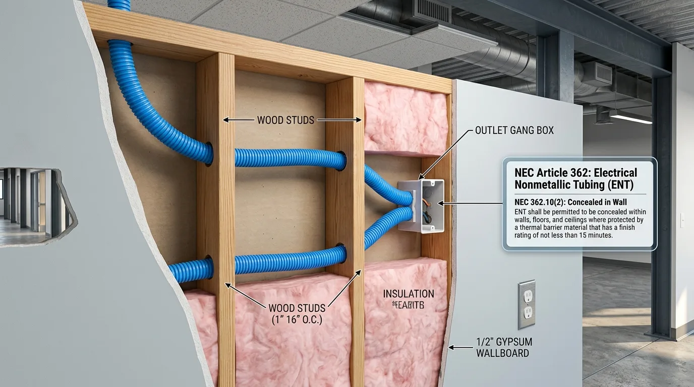
NEC Article 362: Where Can You Legally Install ENT?
Inspectors frequently issue correction notices when ENT is installed in exposed or outdoor locations. NEC Article 362 strictly delineates permitted applications from prohibited environments based on fire resistance ratings and mechanical impact protection.
Permitted Applications (NEC 362.10)
| Location Category | Code Rule | Legal Status | Notes & Conditions |
|---|---|---|---|
| Concealed Drywall Walls | NEC 362.10(1) | PERMITTED | Behind a 15-minute thermal finish (e.g., 1/2″ sheetrock). |
| Poured Concrete Slabs | NEC 362.10(6) | PERMITTED | In slab-on-grade or elevated decks with concrete-tight fittings. |
| Above Drop Ceilings | NEC 362.10(2) | PERMITTED | In accessible T-bar drop ceilings in commercial buildings. |
| Damp Indoor Areas | NEC 362.10(3) | PERMITTED | Indoor locations subject to moisture or wall washing. |
| Embedded in Plaster | NEC 362.10(4) | PERMITTED | Embedded in masonry walls behind finish plaster. |
Prohibited Applications (NEC 362.12)
| Location Category | Code Rule | Legal Status | Notes & Field Solutions |
|---|---|---|---|
| Direct Burial in Earth | NEC 362.12(1) | PROHIBITED | Cannot be buried in dirt. Use Schedule 40 PVC or UF-B. |
| Exposed Outdoors / UV | NEC 362.12(7) | PROHIBITED | Cannot be exposed to direct sunlight unless specifically listed. |
| High Ambient Heat | NEC 362.12(3) | PROHIBITED | Prohibited where ambient temperature exceeds 50°C (122°F). |
| Physical Damage Hazard | NEC 362.12(1) | PROHIBITED | Exposed lower walls subject to impact are not permitted. |
| Commercial Theaters | NEC 362.12(8) | PROHIBITED | Assembly occupancies over 100 persons (use metal raceways). |
ENT Conduit Dimensions & Area Fill Limits (NEC Chapter 9, Table 4)
Because ENT features corrugated exterior and interior walls, its internal diameter (ID) and usable cross-sectional area differ from steel EMT, rigid metallic conduit (RMC), and Schedule 40 PVC.
Under NEC Chapter 9, Table 1, maximum allowable cross-sectional fill limits are:
- 1 Conductor: 53 percent maximum cross-sectional area fill
- 2 Conductors: 31 percent maximum cross-sectional area fill
- 3 or More Conductors: 40 percent maximum cross-sectional area fill
- Short Nipples ($\le 24$ inches): 60 percent maximum fill (NEC Chapter 9, Note 4)
The physical dimensions and allowable fill areas for Electrical Nonmetallic Tubing (ENT) from NEC Chapter 9, Table 4 are compiled below:
| Trade Size | Metric Designator | Nominal Internal Diameter (in) | Total Area 100% (sq in) | 1 Wire Fill 53% (sq in) | 2 Wires Fill 31% (sq in) | 3+ Wires Fill 40% (sq in) | 60% Nipple Fill (sq in) |
|---|---|---|---|---|---|---|---|
| 1/2″ | 16 | 0.602″ | 0.285 | 0.151 | 0.088 | 0.114 | 0.171 |
| 3/4″ | 21 | 0.804″ | 0.508 | 0.269 | 0.157 | 0.203 | 0.305 |
| 1″ | 27 | 1.029″ | 0.832 | 0.441 | 0.258 | 0.333 | 0.499 |
| 1-1/4″ | 35 | 1.360″ | 1.453 | 0.770 | 0.450 | 0.581 | 0.872 |
| 1-1/2″ | 41 | 1.610″ | 2.036 | 1.079 | 0.631 | 0.814 | 1.222 |
| 2″ | 53 | 2.067″ | 3.356 | 1.779 | 1.040 | 1.342 | 2.014 |
NOTE
Field Engineering Rule: Notice that 1/2-inch ENT provides 0.114 sq in of 40 percent fill space, whereas 1/2-inch EMT provides 0.122 sq in. Always use the dedicated ENT column in calculations to prevent overfilling. You can verify mixed conductor configurations with our interactive Conduit Fill Calculator.
Master ENT Conduit Fill Chart: Maximum Conductor Capacities
The tables below provide the maximum number of identical insulated copper conductors permitted in trade sizes 1/2-inch through 2-inch ENT under the standard 40 percent fill rule (3 or more conductors). Values are strictly aligned with NEC Informative Annex C, Table C.2.
Table 1: THHN / THWN / THWN-2 Copper Conductors in ENT
THHN/THWN-2 is the most common conductor pulled through Smurf Tube for commercial and residential branch circuits:
| Conductor Size (AWG / kcmil) | Conductor Area (sq in) | 1/2″ ENT | 3/4″ ENT | 1″ ENT | 1-1/4″ ENT | 1-1/2″ ENT | 2″ ENT |
|---|---|---|---|---|---|---|---|
| 14 AWG | 0.0097 | 10 | 18 | 32 | 58 | 80 | 132 |
| 12 AWG | 0.0133 | 7 | 13 | 23 | 42 | 58 | 96 |
| 10 AWG | 0.0211 | 4 | 8 | 15 | 26 | 36 | 60 |
| 8 AWG | 0.0366 | 2 | 5 | 8 | 15 | 21 | 35 |
| 6 AWG | 0.0507 | 1 | 3 | 6 | 11 | 15 | 25 |
| 4 AWG | 0.0824 | 1 | 1 | 4 | 7 | 9 | 15 |
| 3 AWG | 0.0973 | 1 | 1 | 3 | 5 | 8 | 13 |
| 2 AWG | 0.1158 | 1 | 1 | 2 | 5 | 6 | 11 |
| 1 AWG | 0.1562 | 0 | 1 | 1 | 3 | 5 | 8 |
| 1/0 AWG | 0.1855 | 0 | 1 | 1 | 3 | 4 | 7 |
| 2/0 AWG | 0.2223 | 0 | 1 | 1 | 2 | 3 | 5 |
| 3/0 AWG | 0.2679 | 0 | 0 | 1 | 2 | 3 | 4 |
| 4/0 AWG | 0.3237 | 0 | 0 | 1 | 1 | 2 | 4 |
TIP
Single Conductor Sizing (53% Fill Rule): Where a single conductor is installed (such as a grounding electrode conductor), the 53 percent fill rule applies. For example, a single 1/0 AWG THHN (0.1855 sq in) fits in 3/4″ ENT (53% limit = 0.269 sq in). Compare with metallic raceways using our comprehensive Conduit Fill Chart.
Table 2: XHHW / XHHW-2 Copper Conductors in ENT
XHHW-2 features thicker cross-linked polyethylene insulation, commonly specified for industrial feeds and wet slab environments:
| Conductor Size (AWG / kcmil) | Conductor Area (sq in) | 1/2″ ENT | 3/4″ ENT | 1″ ENT | 1-1/4″ ENT | 1-1/2″ ENT | 2″ ENT |
|---|---|---|---|---|---|---|---|
| 14 AWG | 0.0139 | 7 | 13 | 22 | 40 | 56 | 93 |
| 12 AWG | 0.0181 | 5 | 10 | 17 | 30 | 43 | 71 |
| 10 AWG | 0.0243 | 4 | 7 | 13 | 23 | 32 | 53 |
| 8 AWG | 0.0437 | 1 | 4 | 7 | 12 | 18 | 29 |
| 6 AWG | 0.0590 | 1 | 3 | 5 | 9 | 13 | 22 |
| 4 AWG | 0.0814 | 1 | 1 | 3 | 6 | 9 | 15 |
| 3 AWG | 0.0962 | 1 | 1 | 3 | 5 | 8 | 13 |
| 2 AWG | 0.1146 | 1 | 1 | 2 | 4 | 6 | 11 |
| 1 AWG | 0.1534 | 0 | 1 | 1 | 3 | 5 | 8 |
| 1/0 AWG | 0.1825 | 0 | 1 | 1 | 3 | 4 | 7 |
| 2/0 AWG | 0.2190 | 0 | 1 | 1 | 2 | 3 | 5 |
| 3/0 AWG | 0.2642 | 0 | 0 | 1 | 2 | 3 | 4 |
| 4/0 AWG | 0.3197 | 0 | 0 | 1 | 1 | 2 | 4 |
Mandatory Grounding Rules for ENT (NEC 362.60)
One of the most frequent code infractions cited by municipal electrical inspectors on residential rough-in inspections is omitting the equipment grounding conductor from ENT.
Unlike metallic EMT, IMC, or RMC raceways (which serve as listed equipment grounding conductors under NEC 250.118 when assembled with tight fittings), ENT is completely nonmetallic and nonconductive. It can never carry ground fault current.
WARNING
The Two Critical Grounding Code Rules:
- Mandatory Green Ground Wire (NEC 362.60): An equipment grounding conductor (EGC), bare or insulated with green coloring, must be installed inside the ENT raceway alongside the phase and neutral conductors for every circuit. The ground wire must be sized according to circuit overcurrent protection per NEC Table 250.122 (e.g., 14 AWG Cu for 15A circuits, 12 AWG Cu for 20A circuits, 10 AWG Cu for 30A circuits).
- Ground Wire Counts Toward Conduit Fill (NEC Chapter 9, Note 3): Under Chapter 9, Table 1, Note 3, equipment grounding and bonding conductors must be counted toward total percentage conduit fill. If you pull three 12 AWG phase conductors, one 12 AWG neutral, and one 12 AWG green ground wire, your calculation is based on five conductors, not four.
Step-by-Step ENT Fill Math: Mixed Conductor Sizing Example
When pulling different wire gauges through a single raceway (e.g., branch circuits combined with a larger dedicated feed and a ground wire), Annex C cannot be used directly. You must calculate the exact cross-sectional area of each conductor using NEC Chapter 9, Table 5.
Design Scenario:
An electrician needs to route the following conductors through a single ENT run from a distribution panelboard to a sub-junction box:
- Four (4) 12 AWG THHN copper conductors (two 20-amp, 120V branch circuits)
- Two (2) 10 AWG THHN copper conductors (one 30-amp, 240V equipment feed)
- One (1) 10 AWG bare copper equipment grounding conductor (sized for the 30-amp circuit per NEC 250.122)
Question: What is the minimum standard trade size of ENT required by the NEC?
Mathematical Calculation Breakdown:
Step 1: Determine Total Number of Conductors
Total conductors = 4 (12 AWG) + 2 (10 AWG) + 1 (10 AWG ground) = 7 conductors.
Because the total number of conductors is three or more, the 40 percent conduit fill rule applies.
Step 2: Lookup Individual Conductor Areas (NEC Chapter 9, Table 5)
- 12 AWG THHN cross-sectional area = 0.0133 sq in
- 10 AWG THHN cross-sectional area = 0.0211 sq in
- 10 AWG bare copper conductor area = 0.0150 sq in (or 0.0211 sq in if insulated)
Step 3: Calculate Cumulative Conductor Cross-Sectional Area
- Area for 12 AWG THHN: $4 \times 0.0133\text{ sq in} = \mathbf{0.0532\text{ sq in}}$
- Area for 10 AWG THHN: $2 \times 0.0211\text{ sq in} = \mathbf{0.0422\text{ sq in}}$
- Area for 10 AWG Bare Ground: $1 \times 0.0150\text{ sq in} = \mathbf{0.0150\text{ sq in}}$
- Total Conductor Area $= 0.0532 + 0.0422 + 0.0150 = \mathbf{0.1104\text{ sq in}}$
Step 4: Compare Total Conductor Area to NEC Table 4 ENT Capacities
- 1/2″ ENT allowable 40% area = 0.114 sq in
- 3/4″ ENT allowable 40% area = 0.203 sq in
TIP
Engineering Evaluation & Recommendation:
The total conductor area of 0.1104 sq in is mathematically less than the 0.114 sq in capacity of 1/2-inch ENT (representing 38.7 percent fill).
Practical Jobsite Recommendation: While 1/2-inch ENT is legally compliant by 0.0036 sq in, pulling seven conductors through 1/2-inch corrugated tubing creates severe sidewall friction over any run with bends. Sizing up to 3/4-inch ENT (0.203 sq in / 21.7% fill) is strongly recommended in the field for ease of installation.
NEC 310.15 Ampacity Derating: Thermal Limitations in ENT
Conduit fill is only half the engineering equation. When bundling multiple current-carrying conductors inside a nonmetallic raceway, conductor ampacity derating under NEC 310.15(C)(1) must be applied.
Because ENT is manufactured from plastic PVC, heat generated by electrical current ($I^2R$ resistive heating) cannot radiate outward as quickly as it does through steel EMT or aluminum conduit.
Adjustment Factors for Current-Carrying Conductors (NEC Table 310.15(C)(1))
| Number of Current-Carrying Conductors | Percent Ampacity Derating Factor |
|---|---|
| 1 to 3 | 100% (No derating required) |
| 4 to 6 | 80% |
| 7 to 9 | 70% |
| 10 to 20 | 50% |
| 21 to 30 | 45% |
| 31 to 40 | 40% |
| 41 and above | 35% |
Note: Equipment grounding conductors and neutral conductors carrying only unbalanced current from three-phase or multiwire circuits do not count as current-carrying conductors for derating calculations (NEC 310.15(E)). For thermal verification, use our dedicated Wire Ampacity Calculator.
Practical Derating Example:
If you pull nine 12 AWG THHN conductors (six current-carrying circuit wires + three grounds/neutrals) in 3/4″ ENT:
- 12 AWG THHN 90°C base ampacity = 30 Amperes (NEC Table 310.16)
- 4 to 6 current-carrying wires derate to 80%: $30\text{A} \times 0.80 = \mathbf{24\text{ Amperes}}$
- Applying the NEC 240.4(D) small-conductor rule, maximum overcurrent protection remains 20 Amperes. The circuit passes code without requiring larger wire.
ENT Securing, Supporting & Bending Rules (NEC 362.24 – 362.30)
Because Smurf Tube is flexible, improper securing allows it to sag between framing studs, creating wavy internal cavities that drastically increase wire pulling tension.
Securing & Support Rules (NEC 362.30)
- Securely Fastened Within 3 Feet (900 mm): ENT must be fastened to structural members with listed conduit straps, staples, or cable ties within 3 feet (900 mm) of every box, cabinet, junction box, or termination fitting.
- Supported Every 3 Feet (900 mm): For continuous raceway runs, ENT must be supported at intervals not exceeding 3 feet.
- Exception 1 (Concealed Fished Walls): Where ENT is fished into existing, finished wall cavities where access is blocked, support straps are not required between access points.
- Exception 2 (Luminaire Whips): ENT is permitted in lengths up to 6 feet (1.8 meters) without intermediate support when connecting from a junction box to a luminaire or light fixture above an accessible drop ceiling.
Bending Radii & 360-Degree Bend Limits (NEC 362.24 & 362.26)
- Minimum Bending Radius (NEC 362.24): Bends in ENT must be formed smoothly so the tubing is not damaged or kinked. The minimum bending radius from the inner edge of any bend must comply with NEC Table 2, Chapter 9 (e.g., minimum 4-inch radius for 1/2-inch ENT; 4.5-inch for 3/4-inch; 5.75-inch for 1-inch).
- 360-Degree Total Bend Budget (NEC 362.26): The total degrees of all bends between pull points (boxes, conduit bodies, or panels) must not exceed 360 degrees (the equivalent of four 90-degree quarter bends).
- Pull Box Sizing: Once your conduit run reaches 360 degrees of total bends, you must install an intermediate pull box. For pull box sizing rules, visit our Box Fill & Pull Box Sizing Guide and our 360-Degree Bend Limit Rule Guide.
Concrete Slab Installation: Encasement Best Practices
Embedding ENT inside poured concrete slabs (both on-grade foundations and elevated commercial decks) is one of its most cost-effective applications. However, wet concrete exerts massive hydrostatic buoyant force and crushing pressure during pours.
Follow these jobsite rules to avoid failed pours:
- Use Concrete-Tight Fittings: Standard snap-in dry-location ENT connectors will leak liquid cement slurry into the tubing, creating solid concrete plugs inside your raceway. Always verify fittings carry the stamp “Concrete-Tight” or “Suitable for Concrete Encasement”.
- Anchor to Rebar Grids Every 2 to 3 Feet: Untethered ENT will float to the top surface of liquid concrete during vibrating and screeding. Secure the tubing beneath the upper rebar layer using steel tie wire or heavy-duty nylon cable ties.
- Cap Open Stub-Ups: Seal all open conduit ends with temporary push-in plastic caps before the pour to prevent concrete splash from entering the tube.
- Maintain 2-Inch Concrete Coverage: Maintain at least 2 inches of concrete cover over the ENT to protect against structural cracking and thermal expansion.
ENT vs. EMT vs. Schedule 40 PVC: Comprehensive Comparison Matrix
| Feature / Metric | ENT (Smurf Tube) | EMT (Thinwall Steel) | Schedule 40 PVC |
|---|---|---|---|
| Material | Pliable Corrugated PVC | Rigid Galvanized Steel | Rigid Solid-Wall PVC |
| Governing NEC Article | NEC Article 362 | NEC Article 358 | NEC Article 352 |
| 1/2″ 40% Fill Area | 0.114 sq in | 0.122 sq in | 0.118 sq in |
| Max 12 AWG THHN (40%) | 7 conductors | 9 conductors | 8 conductors |
| Bending Method | Manual by hand (no tools) | Mechanical hand bender | Heat blanket / hot box |
| Equipment Ground Path | Separate copper wire required | Tubing acts as ground path | Separate copper wire required |
| Direct Earth Burial | Prohibited | Permitted (requires corrosion check) | Approved (Direct Burial) |
| Outdoor Sunlight (UV) | Prohibited (unless marked UV) | Approved (Sunlight resistant) | Approved (Sunlight resistant) |
| Poured Concrete Slabs | Approved (Concrete-tight) | Approved | Approved |
| Labor Speed | Extremely fast (roll & snap) | Moderate (cut, ream, bend) | Moderate (glue & prime joints) |
Inspector Red Flags & Apprentice Pitfalls to Avoid
Inspectors frequently fail ENT installations for four preventable reasons:
- Routing ENT Outdoors to Detached Structures: Running blue Smurf Tube underground through garden dirt to a detached shed or garage. This directly violates NEC 362.12(1). Use direct-burial Schedule 40 PVC or UF-B cable.
- Kinking Corrugations on 90-Degree Bends: Forcing ENT around sharp wood corners creates collapsed corrugations. Always maintain sweeping, broad-radius curves.
- Exceeding the 24-Inch Nipple Rule: Taking advantage of the 60 percent fill allowance on runs longer than 24 inches. Note 4 to Chapter 9 Tables restricts the 60 percent fill capacity strictly to conduit pieces not exceeding 24 inches between boxes.
- Ignoring Jam Ratios on 3-Conductor Pulls: When pulling exactly three identical conductors where the ratio of the conduit inside diameter to the conductor outside diameter is between 1.05 and 1.20, wires can wedge into a triangular lock. Verify your installation with our Conduit Jam Ratio Calculator.
Frequently Asked Questions (PAA / FAQs)
Electrical Nonmetallic Tubing earned the trade nickname “Smurf Tube” because the standard color for electrical power branch circuit tubing is bright blue, matching the iconic skin tone of the cartoon Smurf characters.
Yes. NEC Section 362.10(6) permits ENT to be embedded in poured concrete slabs (both elevated structural slabs and slabs on grade), provided that listed concrete-tight fittings are used at all couplings and box terminations to prevent wet cement slurry from entering the raceway.
No. NEC Section 362.12(1) strictly prohibits ENT from being installed in direct burial applications underground. If you need to install underground conduit for outdoor branch circuits or detached buildings, you must install rigid Schedule 40 or Schedule 80 PVC, rigid metal conduit (RMC), or direct-burial cable (UF-B).
Yes. Under NEC Chapter 9, Table 1, Note 3, all equipment grounding and bonding conductors (whether bare, covered, or insulated) must be included in the total cross-sectional area calculation when determining conduit fill.
Under NEC Informative Annex C, Table C.2, a maximum of seven (7) 12 AWG THHN conductors are permitted in 1/2-inch ENT at the 40 percent fill limit. While mathematical division of 0.114 sq in by 0.0133 sq in yields 8 conductors, Annex C Table C.2 sets the legal limit to 7 to prevent binding in corrugated raceways.
Yes. NEC Section 362.10 permits ENT in commercial structures of any construction type (including Type I and Type II high-rise buildings), provided the tubing is concealed behind a thermal barrier with a fire resistance rating of at least 15 minutes, such as 1/2-inch gypsum drywall.
Under NEC 362.30(A), ENT must be securely fastened within 3 feet (900 mm) of every box, cabinet, enclosure, or termination fitting, and supported at intervals not exceeding 3 feet along continuous runs.