
IMPORTANT
Quick Answer: Conduit jam ratio measures the physical space available inside a conduit relative to the outside diameter of conductors being pulled through it. When pulling exactly three conductors of equal size, if the ratio of the conduit inside diameter to a single conductor outside diameter falls between 2.8 and 3.2, the conductors can realign side-by-side in a bend and lock tightly against the conduit walls. This critical window is known as the jam danger zone.
Key Takeaways
- The Core Formula: Jam Ratio = Conduit Inside Diameter ÷ Conductor Outside Diameter.
- The Danger Zone: A jam ratio between 2.8 and 3.2 carries a high risk of severe wedging when pulling three conductors around conduit bends.
- NEC Reference: NEC Chapter 9, Tables Note 2 explicitly alerts designers and installers to the 2.8 to 3.2 jamming threshold.
- Fill Percentage vs. Jam Ratio: A pull can easily pass the NEC 40 percent fill capacity rule yet fail mechanically due to a bad jam ratio.
- The Bend Ovality Factor: Bending conduit flattens its internal cross-section by about 5 percent. Multiplying the conduit inside diameter by 1.05 provides an accurate engineering calculation.
- Primary Prevention Methods: Upsize the conduit trade size, select a thinner conductor insulation type (such as switching from XHHW to THHN), or use factory-triplexed conductors.
What Is Conduit Jam Ratio?
Conduit jam ratio is a geometric relationship that compares the internal size of a raceway to the outer size of the cables inside it. It specifically predicts whether three conductors will wedge tightly against one another and the conduit wall while being pulled around a curve or bend.
Jam Ratio = Conduit Inside Diameter ÷ Conductor Outside DiameterWhen wire jamming occurs, pulling tension spikes instantly. The winch or pulling rope can stretch, conductor insulation can scrape off down to bare copper, or the entire pull can lock up completely, forcing crew members to cut and pull out ruined wire.
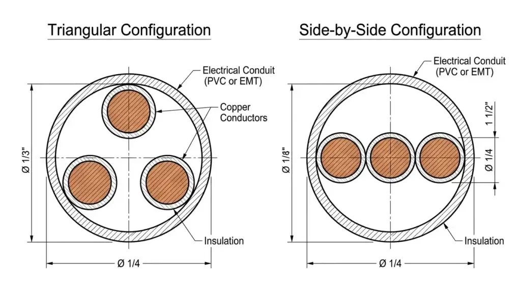
Why Wire Jamming Happens: The Geometric Physics
Wire jamming is a mechanical wedging phenomenon rather than an electrical issue. To understand why it happens, you must look at how conductors behave when moving from straight runs into bends.
In a straight run of conduit, three conductors naturally rest in a triangular or cradled arrangement. Two conductors rest on the bottom of the pipe, and the third sits on top of them. This arrangement is compact and leaves ample free space around the bundle.
When the pull enters a sweep or elbow, the tension on the pulling line changes how the conductors sit. The pull line forces all three conductors toward the inside radius of the bend. Under this force, the top conductor attempts to drop down into the same flat plane as the other two.
If the conduit inside diameter is roughly three times the diameter of a single conductor, all three conductors fit across the conduit width in a single flat row. As they move through the curve, they wedge across the diameter. The force of the pull drives the outer conductors into the conduit walls while squeezing the center conductor between them like a wedge.
The Danger Zone: Why 2.8 to 3.2 Causes Jamming
The physical geometry of three equal circles inside a larger outer circle defines three distinct risk zones.
| Jam Ratio Range | Risk Level | Mechanical Behavior | Action Required |
|---|---|---|---|
| Below 2.8 | Low Risk | Conduit is too narrow for three conductors to fall into a flat side-by-side row. Conductors remain locked in a stable triangular formation. | Proceed with standard pull precautions. Verify conduit fill limits. |
| 2.8 to 3.2 | HIGH DANGER | Conductors can transition into a flat row inside bends. Ovality in bends locks them tightly across the diameter. | Do not pull. Change conduit size or conductor insulation. |
| Above 3.2 | Low Risk | Conduit is wide enough that even if all three conductors lie completely flat, ample clearance remains for them to slide past each other. | Safe to pull. Ensure sidewall bearing pressure is respected. |
WARNING
Why 3.0 Is Not the Only Danger Point: While three conductors theoretically measure exactly 3.0 times their diameter when placed in a flat row, manufacturing tolerances on wire insulation and the minor flattening of conduit in bends expand the real-world danger zone to between 2.8 and 3.2.
Conduit Fill vs. Jam Ratio: The Field Misconception
One of the most frequent mistakes made by installers and designers is assuming that passing NEC conduit fill requirements guarantees a smooth wire pull.
Conduit Fill (governed by NEC Chapter 9, Table 1) limits the maximum percentage of cross-sectional area that conductors can occupy. For three or more conductors, the maximum allowable fill is 40 percent. Conduit fill rules exist primarily to prevent excessive heat buildup during operation and to ensure adequate air circulation.
Jam Ratio is an independent mechanical calculation. It has nothing to do with heat or cross-sectional area. It is entirely about physical geometry during installation.
| Comparison Metric | Conduit Fill (NEC Table 1) | Jam Ratio (NEC Note 2) |
|---|---|---|
| Primary Concern | Thermal Heat Dissipation & Air Flow | Mechanical Clearance in Bends |
| Governing Standard | NEC Chapter 9, Table 1 | NEC Chapter 9, Tables Note 2 |
| Calculation Method | Total Cross-Sectional Area Percentage | Inside Diameter to Outer Diameter Ratio |
| Standard Target | Maximum 40% (for 3 or more conductors) | Outside the 2.8 to 3.2 Danger Zone |
[!COMMON MISTAKE] The 40 Percent Fill Trap: A combination of three 4/0 AWG XHHW-2 conductors in a 2-inch Schedule 40 PVC conduit might calculate to roughly 34 percent conduit fill, which easily passes the 40 percent NEC rule. However, calculating the jam ratio for this exact combination yields a ratio of approximately 2.93, placing it squarely in the middle of the danger zone. Pulling this combination will likely result in a stuck wire pull.
How to Calculate Conduit Jam Ratio (Step-by-Step)
Calculating the jam ratio requires knowing two exact dimensions: the actual inside diameter of the conduit and the actual outside diameter of a single conductor.
Step 1: Find the Conductor Outside Diameter (d)
Look up the overall outer diameter of the conductor in NEC Chapter 9, Table 5, or obtain the exact dimensional cut sheet from the wire manufacturer. Do not use the conductor core size alone; you must include the insulation and jacket thickness.
Step 2: Find the Conduit Inside Diameter (D)
Look up the actual inside diameter of the specific conduit type and trade size in NEC Chapter 9, Table 4. Never use the nominal trade size. A 2-inch trade size conduit does not have an inside diameter of exactly 2.000 inches.
Step 3: Apply the Formula
Divide the conduit inside diameter by the conductor outside diameter.
Jam Ratio = D ÷ dThe 1.05 Bend Ovality Factor
When conduit is bent on the job site using a mechanical bender, or when factory sweeps are manufactured, the round pipe distorts slightly into an oval shape. This ovality flattens the inside diameter along the curve by roughly 5 percent.
To account for this reduction in clearance, engineers multiply the nominal conduit inside diameter by 1.05 when checking for jam potential.
Adjusted Jam Ratio = (1.05 × Conduit Inside Diameter) ÷ Conductor Outside DiameterIf either the standard jam ratio or the adjusted jam ratio falls between 2.8 and 3.2, treat the installation as high risk.
Real-World Calculation Examples Across Conduit Types
Conduit types vary in wall thickness, which means their internal diameters differ even for the same nominal trade size. The table below illustrates how different conduit materials impact the jam ratio when pulling three 3/0 AWG THHN conductors (individual conductor outside diameter = 0.528 inches).
| Conductor Size & Type | Conduit Trade Size & Type | Conduit ID (D) | Calculation (D ÷ d) | Jam Ratio | Status |
|---|---|---|---|---|---|
| Three 3/0 AWG THHN (d = 0.528″) | 2″ EMT | 2.067″ | 2.067 ÷ 0.528 | 3.91 | SAFE (Above 3.2) |
| Three 3/0 AWG THHN (d = 0.528″) | 1-1/2″ EMT | 1.610″ | 1.610 ÷ 0.528 | 3.05 | DANGER (Inside 2.8–3.2) |
| Three 3/0 AWG THHN (d = 0.528″) | 1-1/2″ Schedule 40 PVC | 1.590″ | 1.590 ÷ 0.528 | 3.01 | DANGER (Inside 2.8–3.2) |
| Three 3/0 AWG THHN (d = 0.528″) | 1-1/2″ Schedule 80 PVC | 1.465″ | 1.465 ÷ 0.528 | 2.77 | SAFE (Below 2.8) |
[!PRO TIP] Notice the Schedule 80 Paradox: In the table above, 1-1/2″ Schedule 80 PVC has a smaller inside diameter (1.465″) than Schedule 40 (1.590″). Because the inside diameter is tighter, the jam ratio drops to 2.77, moving it below the 2.8 threshold. While this specific combination avoids jamming, you must verify that it still complies with the NEC 40 percent area fill requirement.
How Conduit Type and Conductor Insulation Impact Jamming
1. Conduit Wall Thickness
- EMT (Electrical Metallic Tubing): Has thin walls, offering the largest inside diameter for any trade size.
- RMC (Rigid Metal Conduit): Has thicker walls than EMT, slightly reducing the inside diameter.
- PVC Schedule 40: Standard wall thickness for underground and exposed runs.
- PVC Schedule 80: Extra-heavy wall thickness designed for areas subject to physical damage. Its substantially smaller inside diameter drastically alters jam ratio calculations compared to Schedule 40.
2. Conductor Insulation Types
- THHN / THWN-2: Features a thin PVC insulation layer with a smooth nylon outer jacket. Its smaller outside diameter often results in higher jam ratios for a given conduit size.
- XHHW-2: Uses cross-linked polyethylene insulation. It is thicker than THHN, which reduces the jam ratio.
- RHH / RHW-2: Has heavy rubber or XLPE insulation, resulting in the largest outside diameter among standard building wires.
IMPORTANT
Always Use Manufacturer Cut Sheets for Precise Work: Cable dimensions in NEC Chapter 9, Table 5 are average values across manufacturers. Actual outer diameters can vary by several hundredths of an inch depending on the brand and manufacturing tolerances. A variation of just 0.02 inches can move a calculation directly into the danger zone.
Job-Site Proven Strategies to Prevent Wire Jamming
If your pre-pull calculation shows a jam ratio between 2.8 and 3.2, take proactive steps before starting the pull.
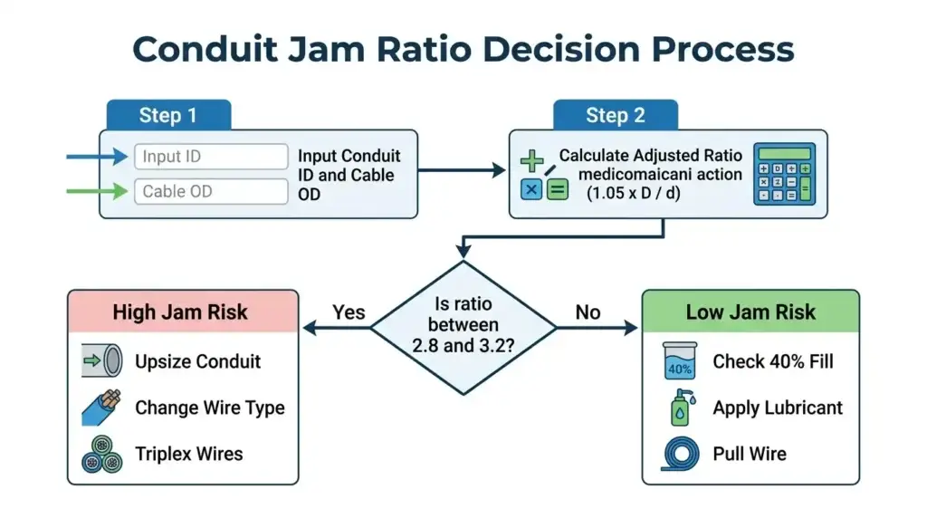
Strategy 1: Increase the Conduit Trade Size
Upsizing the conduit by one trade size is the most direct solution. Increasing from 1-1/2 inch to 2 inch increases the internal diameter significantly, raising the jam ratio well above 3.2.
Strategy 2: Change Conductor Insulation Type
If conduit sizes are fixed by existing structure or conduit banks, select a different conductor insulation. Switching from a thicker insulation like XHHW-2 to a thinner profile like THHN reduces the conductor outside diameter, which increases the jam ratio.
Strategy 3: Order Factory-Triplexed Conductors
Factory-triplexed conductors consist of three single conductors twisted together in a continuous helix during manufacturing. Because the conductors are bound together, they cannot flatten out into a single row when negotiating bends.
Strategy 4: Use Binder Tape on the Job Site
If pulling separate conductors from reels, bind the three conductors together using heavy-duty electrical tape or pulling tape every 3 to 5 feet along the run. This keeps the bundle in a tight triangular formation and prevents individual wires from shifting into a side-by-side alignment.
Strategy 5: Use Premium Polymer Pulling Lubricants
While wire lubricant cannot change geometry, high-performance polymer lubricants significantly reduce the coefficient of friction. Lubricant helps conductors slide past one another rather than catching and wedging when compressed inside a bend.
Troubleshooting a Jammed Wire Pull: What to Do in the Field
If a wire pull stops abruptly and tension spikes, follow these troubleshooting steps immediately.
- Stop Pulling Immediately: Continuing to apply force with a puller when wires are jammed will slice the insulation, stretch the copper conductors, or break the pulling rope.
- Relieve Pulling Tension: Back off the tugger or tension winch slightly to release the physical wedge created inside the conduit bend.
- Attempt to Push Back and Twist: Have crew members at the feed point push the conductors backward a few feet while imparting a counter-clockwise twist to the bundle. This breaks up the flat side-by-side alignment and forces the wires back into a triangular cradle.
- Pump High-Viscosity Lubricant: Inject polymer pulling lube directly into the conduit from both ends and at intermediate pull boxes if accessible.
- Reverse the Pull Direction: If possible, re-rig the pull setup and attempt to pull the wire out in the opposite direction.
Frequently Asked Questions (FAQs)
Technically, jamming can occur with four or more wires, but the physical probability drops significantly. Four or more conductors naturally form complex, interlocking bundles that rarely collapse into a single flat row across the conduit diameter. NEC Chapter 9 Note 2 specifically highlights three conductors because they present the highest geometric risk.
NEC Chapter 9, Tables Note 2 is formatted as an Informational Note in modern code editions. While informational notes are non-enforceable as strict code violations by an inspector, ignoring them can result in physical pull failures, damaged conductors, and costly project delays. Many engineering specifications mandate compliance with jam ratio limits.
Older editions of the National Electrical Code listed the jam ratio range as 2.8 to 3.1. However, field studies, IEEE standard 1185, and major cable manufacturers expanded the recommended danger zone to 2.8 through 3.2 to account for real-world conduit ovality in bends and manufacturing variances in wire insulation.
Pulling at an erratic speed with frequent starts and stops increases the chance that conductors will twist and lock up in a bend. Maintaining a steady, continuous pulling speed keeps constant tension on the bundle, helping it pass smoothly through sweeps.
Practical Summary & Decision Checklist
Before approving a three-conductor pull design, complete this field checklist:
- Step 1: Obtain actual conductor outer diameter (d) from manufacturer spec sheets.
- Step 2: Obtain actual conduit inner diameter (D) for the exact conduit material used.
- Step 3: Multiply conduit inner diameter by 1.05 to account for bend ovality.
- Step 4: Calculate the ratio: Adjusted Ratio = (1.05 × D) ÷ d.
- Step 5: Verify that the ratio is outside the 2.8 to 3.2 danger zone.
- Step 6: Verify that total cross-sectional area fill is less than 40 percent.
- Step 7: If the ratio is between 2.8 and 3.2, select a remediation strategy:
- Upsize conduit trade size
- Change conductor insulation type
- Use triplexed or taped conductors