
IMPORTANT
Quick Summary: Under the National Electrical Code (NEC Article 342 and Annex C Table C.4), Intermediate Metal Conduit (IMC) is engineered from high-strength alloy steel with a thinner wall than RMC, resulting in a larger inside diameter and higher wire capacity while weighing approximately 33% less. When pulling three or more conductors of the same size (THHN/THWN-2 at 40% fill), the standard capacities are:
- 1/2″ IMC: 14 wires of 14 AWG | 10 wires of 12 AWG | 6 wires of 10 AWG | 2 wires of 6 AWG
- 3/4″ IMC: 25 wires of 14 AWG | 18 wires of 12 AWG | 11 wires of 10 AWG | 4 wires of 6 AWG
- 1″ IMC: 41 wires of 14 AWG | 30 wires of 12 AWG | 18 wires of 10 AWG | 7 wires of 6 AWG
- 1-1/4″ IMC: 67 wires of 14 AWG | 49 wires of 12 AWG | 31 wires of 10 AWG | 12 wires of 6 AWG
Key Takeaways
- Higher Wire Capacity Than RMC: Because IMC has a thinner wall than RMC, its interior cross-sectional area is up to 10% to 15% larger, allowing you to pull more conductors per trade size.
- 33% Lighter Than Rigid Steel: IMC provides comparable impact resistance to RMC while being one-third lighter, making overhead installation and field handling significantly easier and faster.
- Interchangeable Threading (NEC Article 342): IMC uses standard National Pipe Thread (NPT) taper threads with a 3/4-inch per foot taper, allowing it to use the exact same threaded couplings, fittings, and locknuts as RMC.
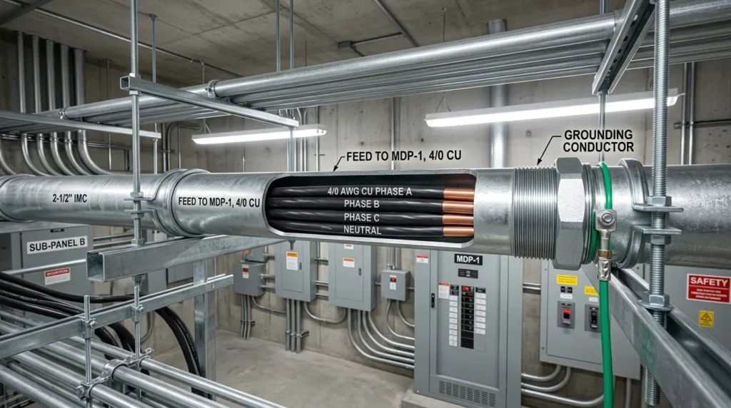
- Approved Equipment Ground (NEC 250.118(3)): Properly assembled threaded IMC conduit is legally recognized as an equipment grounding conductor, often eliminating the requirement to pull a separate green ground wire.
IMC Steel Conduit Advantages At-A-Glance
NEC Article 342 High-Strength Intermediate Metal Conduit
Master IMC Conduit Fill Chart (NEC Annex C Table C.4)
The table below provides the maximum allowable number of conductors for compact copper THHN/THWN-2 conductors inside Intermediate Metal Conduit (IMC) from 1/2 inch to 4 inches based on NEC Chapter 9 Table 4 (40% fill limit for 3 or more wires).
| Conductor Size (AWG/kcmil) | Wire Area (sq. in.) | 1/2″ IMC (0.141 sq. in.) | 3/4″ IMC (0.248 sq. in.) | 1″ IMC (0.400 sq. in.) | 1-1/4″ IMC (0.655 sq. in.) | 1-1/2″ IMC (0.889 sq. in.) | 2″ IMC (1.452 sq. in.) | 2-1/2″ IMC (2.054 sq. in.) | 3″ IMC (3.091 sq. in.) | 3-1/2″ IMC (4.004 sq. in.) | 4″ IMC (5.148 sq. in.) |
|---|---|---|---|---|---|---|---|---|---|---|---|
| 14 AWG THHN | 0.0097 | 14 | 25 | 41 | 67 | 91 | 149 | 211 | 318 | 412 | 530 |
| 12 AWG THHN | 0.0133 | 10 | 18 | 30 | 49 | 66 | 109 | 154 | 232 | 301 | 387 |
| 10 AWG THHN | 0.0211 | 6 | 11 | 18 | 31 | 42 | 68 | 97 | 146 | 189 | 244 |
| 8 AWG THHN | 0.0366 | 3 | 6 | 10 | 17 | 24 | 39 | 56 | 84 | 109 | 140 |
| 6 AWG THHN | 0.0507 | 2 | 4 | 7 | 12 | 17 | 28 | 40 | 60 | 78 | 101 |
| 4 AWG THHN | 0.0824 | 1 | 3 | 4 | 7 | 10 | 17 | 24 | 37 | 48 | 62 |
| 3 AWG THHN | 0.0973 | 1 | 2 | 4 | 6 | 9 | 14 | 21 | 31 | 41 | 52 |
| 2 AWG THHN | 0.1159 | 1 | 2 | 3 | 5 | 7 | 12 | 17 | 26 | 34 | 44 |
| 1 AWG THHN | 0.1339 | 0 | 1 | 2 | 4 | 6 | 10 | 15 | 23 | 29 | 38 |
| 1/0 AWG THHN | 0.1562 | 0 | 1 | 2 | 4 | 5 | 9 | 13 | 19 | 25 | 32 |
| 2/0 AWG THHN | 0.1863 | 0 | 0 | 2 | 3 | 4 | 7 | 11 | 16 | 21 | 27 |
| 3/0 AWG THHN | 0.2223 | 0 | 0 | 1 | 2 | 4 | 6 | 9 | 13 | 18 | 23 |
| 4/0 AWG THHN | 0.2679 | 0 | 0 | 0 | 2 | 3 | 5 | 7 | 11 | 14 | 19 |
| 250 kcmil (MCM) | 0.3970 | 0 | 0 | 0 | 1 | 2 | 3 | 5 | 7 | 10 | 12 |
| 300 kcmil (MCM) | 0.4608 | 0 | 0 | 0 | 0 | 1 | 3 | 4 | 6 | 8 | 11 |
| 350 kcmil (MCM) | 0.5242 | 0 | 0 | 0 | 0 | 1 | 2 | 3 | 5 | 7 | 9 |
| 400 kcmil (MCM) | 0.5863 | 0 | 0 | 0 | 0 | 1 | 2 | 3 | 5 | 6 | 8 |
| 500 kcmil (MCM) | 0.7073 | 0 | 0 | 0 | 0 | 0 | 2 | 2 | 4 | 5 | 7 |
[!PRO TIP] Live Multi-Gauge Calculations: Pulling mixed gauge branch circuits or large parallel feeders? Calculate custom multi-conductor totals instantly with our Interactive Conduit Fill Calculator.
IMC Dimensions and Internal Area Reference (NEC Table 4)
Intermediate Metal Conduit is manufactured with high-strength galvanized alloy steel. The table below outlines internal dimensions and legal fill limits across all trade sizes.
| IMC Trade Size | Internal Diameter (in.) | Total Internal Area (100%) | 1 Wire (53% Fill Limit) | 2 Wires (31% Fill Limit) | 3+ Wires (40% Fill Limit) | 24″ Nipple (60% Fill Limit) |
|---|---|---|---|---|---|---|
| 1/2″ | 0.660 in. | 0.353 sq. in. | 0.187 sq. in. | 0.109 sq. in. | 0.141 sq. in. | 0.212 sq. in. |
| 3/4″ | 0.864 in. | 0.619 sq. in. | 0.328 sq. in. | 0.192 sq. in. | 0.248 sq. in. | 0.371 sq. in. |
| 1″ | 1.105 in. | 1.000 sq. in. | 0.530 sq. in. | 0.310 sq. in. | 0.400 sq. in. | 0.600 sq. in. |
| 1-1/4″ | 1.448 in. | 1.637 sq. in. | 0.868 sq. in. | 0.507 sq. in. | 0.655 sq. in. | 0.982 sq. in. |
| 1-1/2″ | 1.683 in. | 2.222 sq. in. | 1.178 sq. in. | 0.689 sq. in. | 0.889 sq. in. | 1.333 sq. in. |
| 2″ | 2.150 in. | 3.630 sq. in. | 1.924 sq. in. | 1.125 sq. in. | 1.452 sq. in. | 2.178 sq. in. |
| 2-1/2″ | 2.557 in. | 5.135 sq. in. | 2.722 sq. in. | 1.592 sq. in. | 2.054 sq. in. | 3.081 sq. in. |
| 3″ | 3.176 in. | 7.727 sq. in. | 4.095 sq. in. | 2.395 sq. in. | 3.091 sq. in. | 4.636 sq. in. |
| 3-1/2″ | 3.671 in. | 10.010 sq. in. | 5.305 sq. in. | 3.103 sq. in. | 4.004 sq. in. | 6.006 sq. in. |
| 4″ | 4.166 in. | 12.870 sq. in. | 6.821 sq. in. | 3.990 sq. in. | 5.148 sq. in. | 7.722 sq. in. |
• Larger inside diameter
• Up to 15% more wire fill
• Lower material and labor cost
• Heaviest steel raceway
• Standard for severe physical abuse
• Higher material freight cost
Important NEC Installation Rules for IMC Conduit
When engineering and installing Intermediate Metal Conduit, keep these practical code rules in mind:
- Permitted in All Locations (NEC 342.10): IMC is permitted in all atmospheric conditions, direct burial in earth, concrete encasement, and hazardous (classified) locations.
- Standard RMC Thread Compatibility (NEC 342.42): Field-cut threads must use standard pipe dies with a 3/4-inch taper per foot. Standard RMC threaded couplings, conduit bodies, and junction box hubs fit IMC perfectly.
- Approved as Equipment Ground (NEC 250.118(3)): Threaded IMC conduit provides a reliable, low-impedance fault current return path, eliminating the need to pull an extra ground conductor in many branch runs.
- Support Spacing (NEC 342.30): IMC must be securely fastened within 3 feet of each enclosure and supported every 10 to 20 feet depending on conduit trade size. Total bends between pull boxes cannot exceed 360 degrees per our 360-degree conduit bend limit guide.
Frequently Asked Questions (FAQs)
Yes. Because IMC has thinner walls made of high-strength steel alloy, its inside diameter is slightly larger than RMC, allowing it to hold 5% to 15% more conductors depending on trade size.
Yes. Both conduits share the exact same external pipe threading (NPT), allowing you to use standard threaded rigid steel couplings, locknuts, bushings, and conduit bodies interchangeably.
Intermediate Metal Conduit weighs approximately 33% less than standard RMC, significantly reducing worker fatigue and structural load on overhead ceiling trapezes.
Under NEC Annex C Table C.4, you can install up to 11 conductors of 10 AWG THHN in 3/4-inch IMC conduit under the 40% fill limit.
Dedicated IMC Wire Sizing Guides
Explore individual wire gauge fill capacities and specific trade size breakdown tables:
Small Branch Circuit Gauges:
- View capacity limits for 14 AWG in IMC conduit for commercial lighting circuits.
- View capacity limits for 12 AWG in IMC conduit for 20A commercial branch circuits.
- View capacity limits for 10 AWG in IMC conduit for 30A appliance feeds.
Medium Feeder & Subpanel Gauges:
- View capacity limits for 8 AWG in IMC conduit for 40A equipment feeds.
- View capacity limits for 6 AWG in IMC conduit for 50A commercial circuits.
- View capacity limits for 4 AWG in IMC conduit for 70A and 80A feeder drops.
- View capacity limits for 2 AWG in IMC conduit for 100A and 115A feeders.
- View capacity limits for 1 AWG in IMC conduit for 125A commercial feeds.
Heavy Service Entrance & Commercial Cables:
- View capacity limits for 1/0 AWG in IMC conduit for 150A services.
- View capacity limits for 2/0 AWG in IMC conduit for 175A feeders.
- View capacity limits for 3/0 AWG in IMC conduit for 200A commercial feeders.
- View capacity limits for 4/0 AWG in IMC conduit for 225A services.
- View capacity limits for 250 MCM in IMC conduit for commercial distribution mains.
- View capacity limits for 300 MCM in IMC conduit for 300A main feeders.
- View capacity limits for 350 MCM in IMC conduit for parallel switchgear feeds.
- View capacity limits for 400 MCM in IMC conduit for heavy plant distribution.
- View capacity limits for 500 MCM in IMC conduit for commercial service entrances.