
IMPORTANT
Quick Summary: Conduit bending geometry relies on constant trigonometric ratios. With four core mathematical formulas, an electrician can execute any bend with pinpoint accuracy:
- Distance Between Offset Marks:
Offset Depth x Angle Multiplier(e.g., 6″ offset at 30° = 6 x 2.0 = 12 inches between marks).- Conduit Shrink:
Offset Depth x Shrink Factor(e.g., 6″ offset at 30° = 6 x 1/4″ = 1-1/2″ overall length reduction).- 90-Degree Stub-Up Mark:
Desired Height - Bender Deduction(e.g., 14″ stub in 3/4″ EMT = 14″ – 6″ = Mark at 8 inches from end).- 3-Point Saddle Side Marks:
Obstacle Height x 2.5from center mark (using a 45° center bend and 22.5° side bends).
Conduit Offset Multipliers & Shrink Factors
Standard mathematical constants for hand and power benders
Master 90-Degree Stub-Up Deductions & Gain Reference
When making a 90-degree bend, the curved arc of the bender shoe absorbs physical pipe length. To hit an exact stub-up height, you must deduct the bender take-up value from your target dimension.
| Conduit Trade Size | Raceway Type | Standard 90° Deduction (Take-Up) | Typical Bender Gain | Minimum Centerline Radius (NEC Chapter 9 Table 2) |
|---|---|---|---|---|
| 1/2″ Trade Size | EMT Thinwall | 5 inches | 2-5/8 inches | 4.0 inches |
| 1/2″ Trade Size | RMC / IMC Rigid Steel | 6 inches | 3-1/8 inches | 4.0 inches |
| 3/4″ Trade Size | EMT Thinwall | 6 inches | 3-1/4 inches | 4.5 inches |
| 3/4″ Trade Size | RMC / IMC Rigid Steel | 8 inches | 4-0/0 inches | 4.5 inches |
| 1″ Trade Size | EMT Thinwall | 8 inches | 4-1/8 inches | 5.75 inches |
| 1″ Trade Size | RMC / IMC Rigid Steel | 9 inches | 4-5/8 inches | 5.75 inches |
| 1-1/4″ Trade Size | EMT Thinwall | 11 inches | 5-5/8 inches | 7.25 inches |
| 1-1/2″ Trade Size | EMT Thinwall | 14 inches | 7-1/4 inches | 8.25 inches |
| 2″ Trade Size | EMT Thinwall | 16 inches | 8-1/2 inches | 9.50 inches |
NOTE
Understanding Bender Gain: While deduction tells you where to place your pencil mark for a stub, gain is the length saved when routing around a corner rather than traveling to a square 90-degree intersection. For example, on a 3/4″ EMT bend with a 3-1/4″ gain, a 90-degree sweep consumes 3-1/4 inches less total pipe than the sum of the two straight legs.
- Determine desired stub height (e.g., 18 inches to center of junction box).
- Identify the bender take-up (e.g., 6 inches for 3/4″ EMT).
- Calculate pencil mark:
18" - 6" = 12 inches. - Measure 12 inches from the end of the conduit and draw a pencil line.
- Insert pipe into bender, align the Bender Arrow exactly with the 12-inch mark.
- Apply steady foot pressure on the pedal until the conduit is vertical (90 degrees on level).
How to Calculate Offset Bends (Obstacle Navigation)
An offset is composed of two equal, opposite angle bends used to navigate around beams, pipes, or shift the conduit plane into an electrical box knockout.
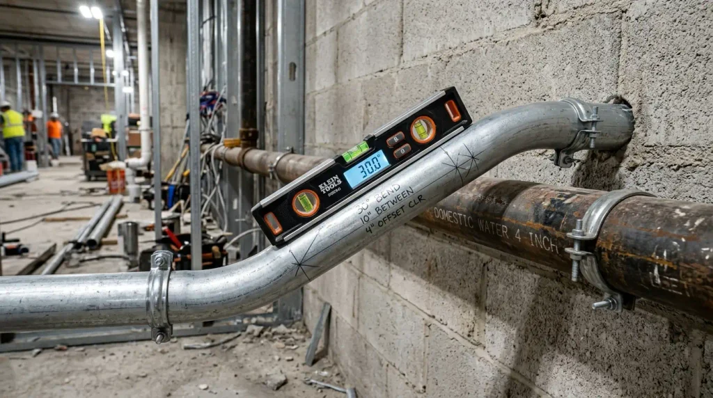
The Two Critical Offset Formulas:
- Distance Between Bends (Travel):
Distance Between Marks = Offset Depth x Multiplier - Total Shrink (Conduit Shortening):
Total Shrink = Offset Depth x Shrink Factor
Real Field Example:
You must cross over an air duct that projects 6 inches off the wall, using 30-degree bends:
- Step 1: Calculate Distance Between Marks: From our multiplier card, the 30° multiplier is 2.0.
Distance = 6 inches x 2.0 = 12 inches between marks. - Step 2: Calculate Conduit Shrink: From our shrink card, the 30° shrink factor is 1/4 inch per inch of offset.
Shrink = 6 inches x 1/4" = 1-1/2 inches. - Step 3: Measure and Mark: Mark your first bend location. Measure forward 12 inches and make your second mark.
- Step 4: Execute the Bends: Align the bender arrow with Mark 1 and bend to 30 degrees. Rotate the pipe 180 degrees, slide to Mark 2, align the arrow, and bend to 30 degrees in the opposite direction.
TIP
Why Shrink Matters: When an offset is formed, the conduit pulls backward toward the obstacle. If your conduit must land in a box knockout 10 feet away, you must add the 1-1/2 inches of shrink to your overall measurement, or the pipe will end up 1-1/2 inches too short!
How to Calculate 3-Point Saddle Bends
A three-point saddle is used to jump over small round obstructions (such as copper water lines or existing conduit runs up to 6 inches in diameter):
- Center Bend Angle: 45 degrees (pointing down over the pipe).
- Side Bend Angles: 22.5 degrees each (returning the pipe flat to the wall).
- Center Mark Placement: Locate the center of the obstacle and add 3/16 inch of shrink per inch of obstacle height.
- Side Mark Placement: Measure outward in both directions from the center mark:
Side Mark Distance = Obstacle Height x 2.5
3-Point Saddle Example (3-Inch Obstacle):
- Shrink Calculation:
3 inches x 3/16" = 9/16 inch. Place your center mark 9/16″ past the obstacle center. - Side Marks Calculation:
3 inches x 2.5 = 7-1/2 inches. Place one mark 7-1/2 inches to the left of the center mark, and another 7-1/2 inches to the right. - Bending Order:
- Align the bender Rim Notch on the center mark and execute a 45-degree bend.
- Rotate pipe 180 degrees, align the Bender Arrow on the first side mark, and execute a 22.5-degree reverse bend.
- Slide to the second side mark, align the Bender Arrow, and execute the final 22.5-degree reverse bend.
Bender Markings Explained: Arrow, Star & Notch
Every professional hand bender features cast symbols with specific geometric functions:
- The Arrow: Marks the start of a 90-degree bend and is the universal alignment point for all offset and kick angles.
- The Star: Marks the back of a 90-degree bend. Used when measuring from the opposite direction (such as executing back-to-back bends to fit between two fixed walls).
- The Rim Notch: Marks the exact center of a 45-degree center bend on a 3-point saddle.
- Degree Lines (10°, 22.5°, 30°, 45°, 60°): Cast indicators on the bender shoe that align parallel with the straight conduit leg to indicate when the desired bend angle is reached.
Common Conduit Bending Mistakes & Fixes
- Dog-Legging on Offsets: Occurs when the conduit is not rotated exactly 180 degrees between bends. The offset twists out of plane and will not lay flat against the wall. Fix: Sight down the length of the conduit or lay the pipe on a flat floor before executing the second bend.
- Under-Bending or Springback: Steel conduit naturally springs back 1 to 2 degrees after releasing foot pressure. Fix: Overbend slightly past the angle mark (e.g., bend to 31° to achieve a true 30° angle).
- Pinch Wrinkling: Caused by pulling with the bender handle rather than applying firm, steady downward foot pressure on the foot pedal. Fix: Keep 90% of your body weight driving down through the foot pedal.
- Exceeding the 360-Degree Code Limit: NEC 358.26 limits total bends between pull boxes to 360 degrees. An offset (two 30° bends = 60°) plus three 90° stubs (270°) equals 330°, leaving only 30° of allowable curvature before a pull box is mandatory. Review our 360-degree conduit bend limit guide to plan legal pull routes.
Frequently Asked Questions (FAQs)
The multiplier for a 30-degree bend is 2.0. To find the distance between your two bend marks, multiply the offset depth by 2.0 (e.g., a 5-inch offset requires 10 inches between marks).
Conduit shrinks 1/4 inch (0.25″) per inch of offset depth at 30 degrees. For a 4-inch offset, the pipe shrinks a total of 1 inch.
The standard stub-up deduction for 3/4-inch EMT conduit is 6 inches. To create a 15-inch stub-up, place your pencil mark at 9 inches (15″ – 6″).
Yes. 1-inch EMT can be bent with a hand bender, but it requires significant body weight and strong foot pressure. Ensure the bender foot pedal is fully engaged to prevent kinking.
Related Sizing Tools & Authority Guides
Explore Master Raceway Fill Hubs:
- Verify wire capacity with our EMT conduit fill chart guide.
- Verify heavy steel capacity with our RMC rigid metal conduit fill guide.
- Sizing intermediate steel? Check the IMC conduit fill chart guide.
Code Rules & Comparison Guides:
- Evaluate job costs with our Conduit Bending vs Factory Elbows guide.
- Understand pull limits with our 360-degree conduit bend limit guide.
- Take advantage of short runs using the 24-inch nipple 60 percent fill rule.
- Calculate custom multi-conductor combinations with our Interactive Conduit Fill Calculator